Jk Electrocorps | Best IEEE Project center in Chennai shows you how a Bio Metric security system works .
Bio metric Security System using Arduino and Fingerprint Sensor
Security is a major concern in our day to day life, and digital locks have become an important part of these security systems. There are many types of security systems available to secure our place. Some examples are PIR based Security System, RFID based Security System, Digital Lock System, bio-matrix systems, Electronics Code lock. In this post, we will Interface a Fingerprint Sensor Module with Arduino and will build a Fingerprint based Biometric Security System with door locking. Finger Print is considered one of the safest key to lock or unlock any system as it can recognize any person uniquely and can’t be copied easily.
Components Required:
- Arduino Uno
- Finger Print Module
- Push Button -4
- LEDs -2
- 1K Resistor -3
- 2.2K resistor -1`
- Power Supply
- Connecting wires
- Cardboard Box
- Servo Motor -1
- 16x2 LCD -1
- Bread Board -1
Working Explanation:
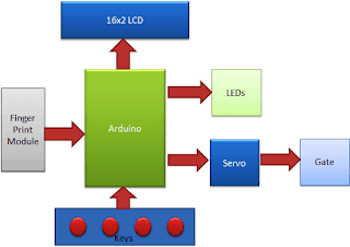
Working of this Fingerprint Sensor Door Lock is easy. In this project, we have used a gate that will be open when we place stored finger at the finger print module. First of all, the user needs to enroll finger with the help of push button/keys. To do this user need to press ENROLL key and then LCD asks for entering location/ID where finger will be a store. So now user needs to enter ID (Location) by using UP/DOWN keys. After selecting Location/ID user needs to press an OK key (DEL key). Now LCD will ask for placing finger over the finger print module. Now user needs to put his finger over finger print module. Then LCD will ask to remove the finger from finger print module and again ask for placing the finger. Now user needs to put his finger again over finger print module. Now finger print module takes an image and converts it into templates and stores it by selected ID in to the finger print module’s memory. Now user can open the gate by placing the same finger that he/she have added or enrolled into the system and then press MATCH key (UP/Down key). By the same method, the user can add more fingers. Check the Video below for full demonstration.
Now if the user wants to remove or delete any of stored ID then he/she need to press DEL key, after pressing DEL key, LCD will ask for select location means select ID that to be deleted. Now user needs to select ID and press OK key (same DEL key). Now LCD will let you know that finger has been deleted successfully. Now the user may check it was deleted or not by placing the same finger over the finger print module and pressing MATCH key (UP/Down key).
When placed finger will be valid Green LED will glow for five second and gate also opens at the same time. After 5-seconds gate will be closed automatically. The user may customize gate/door opening and closing according to their requirement. Servo motor is responsible for open and closing of the gate.
Circuit Explanation:
The circuit of this Arduino Fingerprint Security System is very simple which contains Arduino which controls whole the process of the project, push button, buzzer, and LCD. Arduino controls the complete processes.
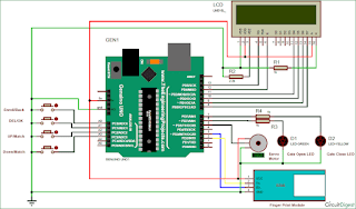
The push button is directly connected to pin D14(ENROL),D15(DEL), D16(UP) and D17(DOWN) of Arduino with respect to ground And Yellow LED is connected at Digital pin D7 of Arduino with respect to ground through a 1k resistor and Green LED is connected to D6 of Arduino with the same method. Finger Print Module’s Rx and Tx directly connected at Software Serial or Digital pin D2 and D3 of Arduino. 5v supply is used for powering finger print module taken from Arduino board and Servo motor is also connected to PWM pin D5 of Arduino. A 16x2 LCD is configured in 4-bit mode and its RS, EN, D4, D5, D6, and D7 are directly connected at Digital pin D13, D12, D11, D10, D9, and D8 of Arduino.


Comments
Post a Comment